Adding USB-C to an Arduino Pro Micro
I’m writing this post mainly because I often find myself having to add an external USB-C connector to the Arduino Pro Micros I use in some projects, but never fail to fall into the same traps and spend an hour or two trying to diagnose why a seemingly simple modification never works at the first try. Being tired of bringing out the ‘scope and the logic analyzer and always ending up with the same result of having simply misplaced a wire, let me document the trick a tad better for the people of the Internet to benefit from.
The curlprit
Getting 5V from USB is usually a simple matter - even if USB-C technically needs some more work, see these specs, page 8, Table 3 - but what might trip you up is the reference voltage for the USB differential data signals. If the voltage coming out of the USB bus isn’t referenced correctly on the target board, in this case the Pro Micro, chances are that you’ll get power but no data transfer.
The solution
Luckily SparkFun has readily available schematics and PCB designs for the Pro Micro (store, GitHub), so exploring them and figuring out where to connect the D+ and D- lines is a fairly easy job.
Even if this board is widely regarded as an official Arduino product, I was surprised to discover that it’s really just a SparkFun spinoff (and/or random clones) derived from the original Arduino Micro.
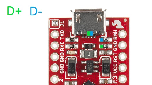
For the sake of simplicity I’ll borrow KindDubDub‘s drawing from the Arduino forums:

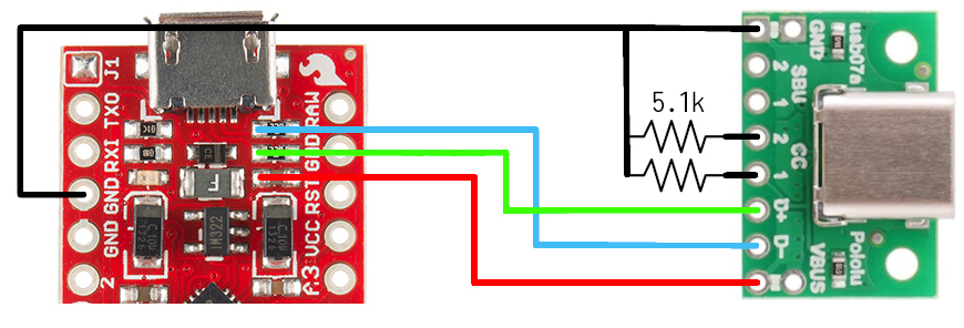
What this drawing doesn’t show and the schematics may not make immediately obvious, though, is that even though the data lines of the external connector can be soldered to those two resistors and ground can go to, well, any ground pad… If you connect the voltage bus onto the nearby VCC pin that feeds the board’s regulator chances are that you won’t get any valid USB data signals! A place that correctly references the external voltage even in most cheap clones of the Pro Micro is the capacitor right next to those two resistors, making the final wiring look something like this:

Obviously the ground wire can go to any GND pad (and in most clones even to the shell of the USB-Micro connector and its relative mounting pads), it was just impractical to cross the data lines in this drawing.
I’ll let search engines do their job in indexing this post and hope that it will help fellow stuck tinkerers out in the future.